Natural Gas Special Trap 80
Overview
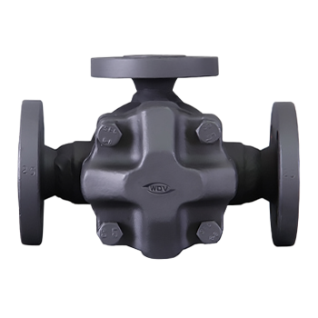
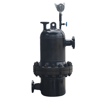
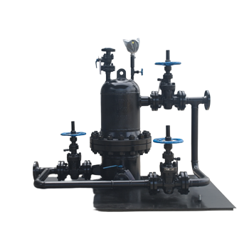
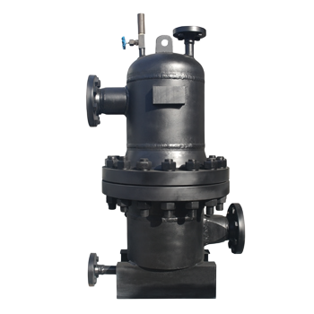
Natural gas trap valve
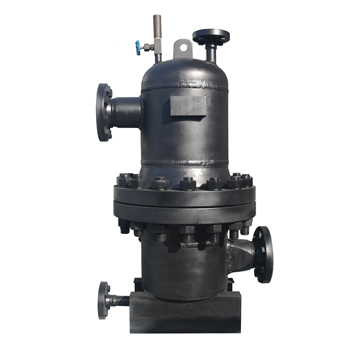
TSS43H series natural gas trap valve is a fully automatic liquid discharge device, the product that sedimentary water gas water separator or gas tank gas in power without the use of other conditions (liquid) to achieve automatic discharge, waste water (liquid) without gas leakage in the process of avoiding artificial schedule (liquid) caused by natural gas losses (about 1% of production), to ensure supply of quality, purifying the environment, the implementation of cleaner production, eliminate safety hazards and improving working conditions have a remarkable effect.
:
1、 100%。
functional features:
1、all-weather automatic continuous operation, there is water on the row, no water automatic shutdown, sink water (liquid) discharge rate of 100%.
2、gas tight, no gas leakage in operation, the leakage rate is zero.
3、automatic settlement of dirt, the implementation of regular sewage.
4、the internal material for all stainless steel, inside the valve to avoid corrosion treatment, long service life.
5、easy installation, no debugging, smooth operation, safe and reliable.
Technical characteristics:
Model
Nominal diameter
(mm)
(MPa)
Working pressure
(MPa)
working temperature
(℃)
Displacement
(M3/h)
Leak
rate
(%)
Drainage
rate
(%)
TSS43H-16
25
32
40
50
65
80
100
150
1.6
≤1.6
Ambient temperature
2-50
0
100
TSS43H-25
2.5
≤2.0
TSS43H-40
4.0
≤3.0
TSS43H-63
6.3
≤5.0
TSS43H-100
10.0
≤8.0
:
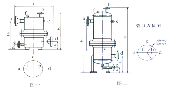
Outline drawing:a、Intake b、Air return port c、Inspection Gate d、Outfall e、sewage outfalls f、Reserve portM20×1.5Plug
:
model, specification, work parameter year, installation size:
TSS43H natural trap according to the liquid can be divided into different components of A series and B series of two.
The A series means that the liquid is water free and has no other liquid components (Table 1).
The B series represents a mixture of liquids that can be dispersed as oil or water and condensate (table two).
If natural gas contains H2S gas, sulfur resistant natural gas traps shall be selected. The type of sulfur resistant natural gas trap is common type of natural gas trap, plus "K"". The model in the table is the anti sulfur trap of the corresponding model.
|
Model |
Specif ication number |
Nominal pressure (MPa) |
Working parameter |
Installation size |
Exit |
Compreh ensive Descr iption |
||||||
|
Working pressure (MPa) |
Displa cement (M3/h) |
H1 mm |
H2 mm |
H3 mm |
L mm |
Icon |
DN mm |
PN MPa |
||||
|
TSS43H-16 (KTSS43H-16)
|
A1 |
1.6 |
0.8 |
2 |
500 |
200 |
680 |
540 |
40
50
65
80
100 |
1.6 |
DN40, H4=100mm; DN15, JB/T81 -94 PN≤10MPa JB/T 82.2-94A |
|
|
A2 |
5 |
600 |
200 |
780 |
600 |
|||||||
|
A3 |
10 |
730 |
200 |
910 |
600 |
|||||||
|
A4 |
15 |
850 |
200 |
1030 |
630 |
|||||||
|
A5 |
1.5 |
2 |
500 |
200 |
680 |
540 |
||||||
|
A6 |
5 |
600 |
200 |
780 |
600 |
|||||||
|
A7 |
10 |
730 |
200 |
910 |
600 |
|||||||
|
A8 |
15 |
730 |
200 |
910 |
630 |
|||||||
|
TSS43H-25(KTSS43H-25)
|
A9 |
2.5 |
2.0 |
2 |
500 |
200 |
680 |
540 |
2.5 |
|||
|
A10 |
5 |
600 |
200 |
780 |
600 |
|||||||
|
A11 |
10 |
860 |
200 |
1040 |
600 |
|||||||
|
A12 |
15 |
880 |
200 |
1060 |
630 |
|||||||
|
TSS43H-40 (KTSS43H-40) |
A13 |
4.0 |
3.0 |
2 |
580 |
200 |
750 |
540 |
4.0 |
|||
|
A14 |
5 |
600 |
200 |
770 |
600 |
|||||||
|
A15 |
10 |
880 |
320 |
1180 |
630 |
|||||||
|
A16 |
15 |
1000 |
320 |
1320 |
630 |
|||||||
|
TSS43H-63 (KTSS43H-63) |
A17 |
6.3 |
4.5 |
2 |
710 |
200 |
900 |
540 |
6.3 |
|||
|
A18 |
5 |
730 |
200 |
920 |
600 |
|||||||
|
A19 |
10 |
1000 |
320 |
1320 |
630 |
|||||||
|
A20 |
15 |
1150 |
320 |
1470 |
630 |
|||||||
|
A21 |
5.5 |
2 |
710 |
200 |
900 |
540 |
||||||
|
A22 |
5 |
730 |
200 |
920 |
620 |
|||||||
|
A23 |
10 |
1000 |
320 |
1320 |
630 |
|||||||
|
TSS43H-100 (KTSS43H-100) |
A24 |
10.0 |
6.0 |
2 |
710 |
200 |
900 |
540 |
10.0 |
|||
|
A25 |
5 |
730 |
200 |
920 |
620 |
|||||||
|
A26 |
10 |
1120 |
340 |
1140 |
680 |
|||||||
|
A27 |
8.0 |
2 |
880 |
340 |
1180 |
620 |
||||||
|
A28 |
5 |
1120 |
340 |
1420 |
620 |
|||||||
|
A29 |
10 |
1120 |
340 |
1440 |
680 |
|
||||||
|
Model |
Specif ication number |
Nominal pressure (MPa) |
Working parameter |
Installation size |
Exit |
Compreh ensive Descr iption |
||||||
|
Working pressure (MPa) |
Displa cement (M3/h) |
H1 mm |
H2 mm |
H3 mm |
L mm |
Icon |
DN mm |
PN MPa |
||||
|
TSS43H-16 (KTSS43H-16) |
B1 |
1.6 |
0.8 |
2 |
700 |
200 |
880 |
540 |
40
50
65
80
100
|
1.6 |
1 DN40, PN H4=100mm; 2 DN15, PN 3 PN≤ 2.5MPa JB/T81-94 2.5<PN ≤10Mpa JB/T 82.2-94A |
|
|
B2 |
5 |
730 |
200 |
910 |
600 |
|||||||
|
B3 |
10 |
850 |
200 |
1030 |
630 |
|||||||
|
B4 |
1.5 |
2 |
700 |
200 |
880 |
540 |
||||||
|
B5 |
5 |
850 |
200 |
1030 |
600 |
|||||||
|
B6 |
10 |
850 |
200 |
1030 |
600 |
|||||||
|
TSS43H-25 (KTSS43H-25) |
B7 |
2.5 |
2.0 |
2 |
700 |
200 |
880 |
540 |
2.5 |
|||
|
B8 |
5 |
730 |
200 |
910 |
600 |
|||||||
|
B9 |
10 |
1030 |
320 |
1350 |
630 |
|||||||
|
TSS43H-40 (KTSS43H-40) |
B10 |
4.0 |
3.0 |
2 |
600 |
200 |
980 |
600 |
4.0 |
|||
|
B11 |
5 |
850 |
200 |
1030 |
600 |
|||||||
|
B12 |
10 |
1030 |
320 |
1350 |
630 |
|||||||
|
TSS43H-63 (KTSS43H-63) |
B13 |
6.3 |
4.5 |
2 |
730 |
200 |
910 |
600 |
6.3 |
|||
|
B14 |
5 |
1000 |
320 |
1320 |
630 |
|||||||
|
B15 |
10 |
1150 |
320 |
1450 |
630 |
|||||||
|
B16 |
5.5 |
2 |
730 |
200 |
910 |
600 |
||||||
|
B17 |
5 |
1030 |
320 |
1350 |
630 |
|||||||
|
TSS43H-100 (KTSS43H-100) |
B18 |
10.0 |
6.0 |
2 |
850 |
200 |
1030 |
620 |
10.0 |
|||
|
B19 |
3 |
980 |
200 |
1160 |
620 |
|||||||
|
B20 |
8.0 |
2 |
1150 |
340 |
1470 |
620 |
||||||
|
B21 |
3 |
1150 |
340 |
1470 |
620 |
|||||||
Installation and maintenance:
1, the valve should be installed horizontally in the pipeline, the lower position, the valve should be installed before the cut-off valve, filter bypass valve installed at the same time.
2, the trap installed, open the inlet stop valve, and then open the outlet valve, the trap began to run normally, drainage continuous operation.
3. Installation direction: the arrow on the valve body is in line with the direction of the fluid in the pipe (arrow pointing to the outlet of the fluid).
4, sewage clearance: as a result of long-term accumulation, with the condensate into the trap cavity, there will be a certain amount of slag.
5, sewage operation: close the trap before and after the cut-off valve, and then open the bottom dirty ball valve, and then slowly open the inlet stop valve, with condensed water to wash the valve cavity slag, until the rinse clean inside.
6, in order to prevent slag into the trap, according to the user's respective pipe conditions, regular cleaning debris, can make trap to maintain good normal work.