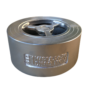
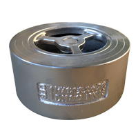
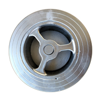
Wafer Check Valves
Overview
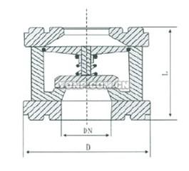
The clip check valve is composed of valve body, valve disc, spring and so on. It is installed horizontally or vertically to the pipeline system to prevent the reverse flow of the medium.
Wafer type check valve for the nominal pressure of PN10 ~ PN420, Class150 ~ Class2500; the nominal diameter of DN15 ~ DN1200, NPS1/2 ~ 48; all kinds of pipeline working temperature of -196 DEG C to 540 DEG C, used to prevent the media back. By selecting different materials, the clip check valve can be applied to many kinds of media such as water, steam, oil, nitric acid, acetic acid, strong oxidizing medium and urea in petrochemical, metallurgical, power, light industry and food industries.
Product structure:
1. short length of the structure, the length of the structure is only the traditional flange check valve 1/4 ~ 1/8;
2. small, light weight, and its weight is only 1/4 to 1/20 of the traditional flange check valve;
3. valve closes fast, water hammer pressure is small;
4. horizontal pipe or vertical pipe can be used and easy to install.
The flow path of the 5. pair clip check valve is smooth and the fluid resistance is small.
6. the action is sensitive and the sealing performance is good.
The 7. valve stroke is short and the impact force of the valve is small.
8. overall structure, simple and compact, beautiful appearance;
9. long life and high reliability.
Material for the main parts of the clip check valve:
|
Part name |
、 Valve body, valve cover, valve disc |
Sealing surface |
rocker |
Pin shaft |
Shim |
|
Part material |
carbon steel |
Hardfacing hard alloy |
carbon steel |
Chromium stainless steel |
+304 Flexible graphite+304 |
Part material
|
Model |
Valve body |
Valve clack |
Spring |
|
H71H-16Q 、H71H-25Q |
QT400-15 |
25 |
50CrVA |
|
H71W-25H、 H71W-40H |
2Cr13 |
1Cr13 |
1Cr18Ni9Ti |
|
H71W-25P 、H71W-40P |
ZG1Cr18Ni9Ti |
1Cr18Ni9Ti |
1Cr18Ni9Ti |
Technical parameter
|
Nominal pressure (MPa) |
Applicable temperature(℃) |
Applicable medium |
|||
|
H71H-16Q |
1.6 |
2.4 |
1.76 |
≤235℃ |
|
|
H71H-25Q |
2.5 |
3.75 |
2.75 |
≤235℃ |
|
|
H71W-25H |
≤300℃ |
||||
|
H71W-25P |
≤200℃ |
||||
|
H71W-40H |
4.0 |
6.0 |
4.4 |
≤300℃ |
|
|
H71W-40P |
≤200℃ |
||||
|
|
Main shape size:
|
L |
D |
|||
|
1.6 |
2.5 |
4.0 |
||
|
15 |
25 |
48 |
48 |
48 |
|
20 |
31.5 |
58 |
58 |
58 |
|
25 |
35.5 |
68 |
68 |
68 |
|
32 |
40 |
80 |
80 |
80 |
|
40 |
45 |
90 |
90 |
90 |
|
50 |
56 |
105 |
105 |
105 |
|
65 |
63 |
125 |
125 |
125 |
|
80 |
71 |
140 |
140 |
140 |
|
100 |
80 |
160 |
165 |
165 |
|
125 |
110 |
190 |
195 |
195 |
|
150 |
125 |
215 |
225 |
225 |
|
200 |
160 |
270 |
285 |
290 |
|
250 |
200 |
330 |
340 |
350 |
|
300 |
250 |
385 |
400 |
415 |
1、
2、
3、
4、
Installation and use
1, the valves at both ends of the valve must be blocked, and there is a dry and ventilated room. Corrosion protection should be regularly checked for long-term storage.
2, before installation, the valve should be cleaned and the defects caused in the transportation process are eliminated.
3, the installation must carefully check the sign on the valve and whether the nameplate is in accordance with the requirements.
4. The valve is installed on the horizontal pipe and the valve cover is upwards.