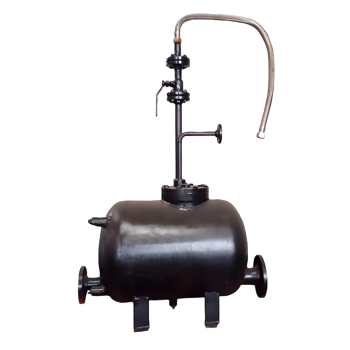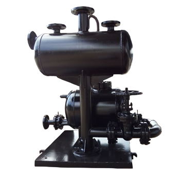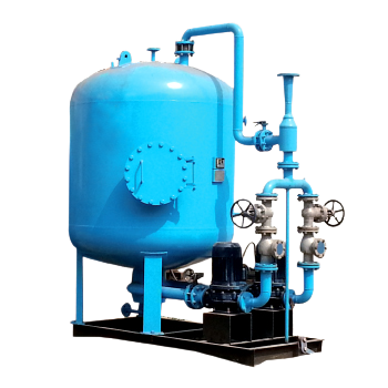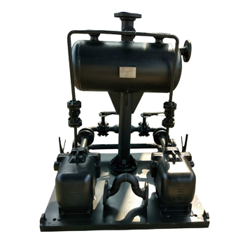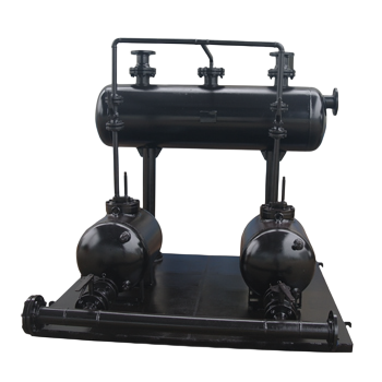
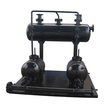
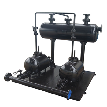
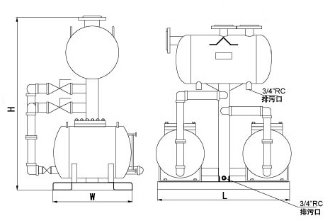
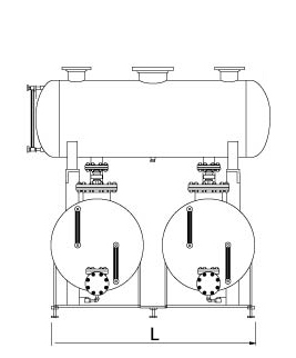
Double Pump Condensed Water Recovery Device WDVSP2X5T
Overview
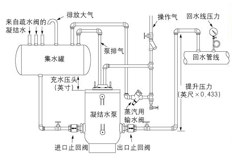
Automatic and typical installation of condensate water collecting tank with opening
Condensate water automatic pump will discharge the condensed water that contained in open water collector into high jump stand condensate water return pipe with possible existence of pressure.For safety,it`s advisable to adopt the exhaust valve and water collector with ventilation whenever using steam driving.
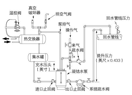
Typical installation of closed system condensate water automatic pump
Condensate water will be discharged from apressure system to another rather high-pressure system.it`s possible that both inlet tube and return pipe are rose,such installation method could be used in the water collector with pressure,also applicable to the equipment with high volume of liquid dispensing.
A schematic diagram for the installation of the condensate control pump in the atmospheric water tank
Basic principle
The condensate control pump belongs to a pressure control pump and is mainly designed for situations where electricity is not applied to pump condensate or other fluids. Compared with the traditional water pump, the condensate control pump is especially suitable for the "difficult" medium, such as high temperature condensate water or corrosive fluid. Pressure operated pumps, especially condensate control pumps, are recognized as long - lived, rarely - maintained pumps. Because the pump has no rotary seal structure, no motor and pump impeller, the service life is usually five to ten times of the traditional electric pump, and at the same time, most of the general maintenance is omitted.
1, the high temperature condensate is sent back to the boiler, the chemical treatment agent of boiler water supply is saved, and the cost of reheating the feed water of the manufacturing material boiler is reduced.
2, the pump does not need electrical maintenance.
3, the pump can be safely used in dangerous or explosive environments.
4. According to the different models, the steam, compressed air or other gas can be controlled by the pressure of 0.5 to 1.6Mpa.
5. The maximum amount of water thinning up to 22000Kg/h.
The condensate control pump is discharged from the steam or compressed gas. The floating ball is connected to the connecting rod and the spring, and the intake valve and the exhaust valve are also driven. In the liquid filling cycle, the intake valve is closed and the exhaust valve opens, so that the condensate is filled into the pump body. When the floating ball rises with the level of the liquid level to the point of its stroke, the switch control mechanism opens the spring, opens the intake valve, and closes the exhaust valve. Steam or compressed gas flow into the pump and discharge the liquid. A reverse check valve is installed at the inlet and outlet of the pump to make the liquid flow in the direction of the reverse check valve.
|
(bar) Operation pressure |
(bar) Total backpressure |
|||||
|
1”×1” |
1-1/2”×1-1/2” |
2”×2” |
3”×2” |
3”×2” Dual |
||
|
0.34 |
0.14 |
1877 |
3455 |
5340 |
6264 |
12528 |
|
0.69 |
0.34 |
1886 |
3161 |
4413 |
5039 |
10077 |
|
|
0.14 |
2550 |
4704 |
6600 |
8010 |
16019 |
|
1.72 |
1.03 |
1795 |
2747 |
3480 |
3870 |
7739 |
|
|
0.69 |
2202 |
3534 |
4460 |
5088 |
10175 |
|
|
0.34 |
2648 |
4766 |
6255 |
7527 |
15054 |
|
3.45 |
2.76 |
1301 |
1873 |
2351 |
2535 |
5071 |
|
|
1.72 |
1974 |
2903 |
3456 |
3828 |
7655 |
|
|
0.69 |
2132 |
4194 |
5678 |
6699 |
13397 |
|
5.17 |
4.14 |
1266 |
1756 |
2146 |
2299 |
4597 |
|
|
2.76 |
1854 |
2601 |
3025 |
3306 |
6612 |
|
|
1.03 |
1758 |
3626 |
5453 |
6381 |
12762 |
|
6.90 |
5.52 |
1235 |
1673 |
2013 |
2146 |
4292 |
|
|
4.14 |
1642 |
2224 |
2564 |
2769 |
5538 |
|
|
2.76 |
2077 |
3001 |
3365 |
3711 |
7422 |
|
|
1.03 |
1255 |
29.6 |
5404 |
6472 |
12946 |
|
8.62 |
7.93 |
887 |
1353 |
1631 |
1722 |
3444 |
|
|
6.90 |
1207 |
1611 |
1916 |
2037 |
4075 |
|
|
5.52 |
1512 |
2007 |
2302 |
2469 |
4938 |
|
|
4.14 |
1848 |
2506 |
2827 |
3072 |
6144 |
|
|
2.76 |
1810 |
3271 |
3620 |
4016 |
8033 |
|
|
1.72 |
11337 |
3064 |
4869 |
5608 |
11215 |
|
10.34 |
8.28 |
1212 |
1601 |
1889 |
2004 |
4007 |
|
|
6.9 |
1440 |
1886 |
2156 |
2302 |
4604 |
|
|
5.52 |
1710 |
2261 |
2549 |
2745 |
5491 |
|
|
4.14 |
2029 |
2881 |
3180 |
3468 |
6936 |
|
|
2.76 |
1539 |
3217 |
3848 |
2023 |
8591 |
|
|
1.72 |
1052 |
2601 |
4716 |
5502 |
11005 |
|
The ratio of backpressure to driving pressure |
||||||||
|
10% |
20% |
30% |
40% |
50% |
60% |
70% |
80% |
90% |
|
1.04 |
1.06 |
1.08 |
1.10 |
1.12 |
1.15 |
1.18 |
1.23 |
1.28 |
|
Water filled head (inch) |
|||||
|
1” |
1-1/2” |
2” |
3”×2” |
4” |
|
|
6 |
0.70 |
0.70 |
0.70 |
0.84 |
- |
|
1 |
1.00 |
1.00 |
1.00 |
1.00 |
0.7 |
|
2 |
1.20 |
1.20 |
1.20 |
1.08 |
1.00 |
|
36 |
1.35 |
1.35 |
1.35 |
1.20 |
1.10 |
|
48 |
- |
- |
- |
- |
1.15 |
|
model |
Drainage amount |
Weight |
(Mpa) Nominal pressure |
|||
|
H |
W |
L |
||||
|
WDVSP2X5T |
1699.5 |
1740 |
1900 |
10T/h |
|
1.6 |
2、
Installation and start operation
install
1, the installation location of condensate control pump should ensure that all upstream condensate discharged into the pump can be discharged smoothly, and the recommended inlet pressure head is 12 "(305mm), which can correctly introduce operation steam or compressed air.
2, in the operation of steam, above the pipeline interface must be located in the operation of a steam main pipe, is prohibited under the main pipe is arranged on the main pipeline, to avoid water and impurities into the operation of the steam pipe.
3, if the condensate pump control is used to recover the more hydrophobic point discharge condensate, taking into account the different hydrophobic point exhaust condensation water have different residual pressure, to prevent the mutual interference between different hydrophobic, suggested in the condensed water control pump installed before the water collecting tank, collecting tank size is opinion table.
4. The check valve must be installed in the inlet and outlet of the condensate control pump to ensure the normal operation of the condensate control pump. It is suggested that the check valve provided by our company should be used to ensure the drainage of the pump.
5. The installation of the condensate control pump for the open system is shown in the diagram.
6, the total weight of the water pump to control the setting in place carrying capacity is greater than the full of the ground. The surface of the foundation should be smooth and clean.
7, before condensing water enters and enters the condensate control pump, the pipeline of the system must be swept away, so as to avoid contaminants in the system, such as welding slag and rust, and enter the condensate control pump, which will damage the components of the pump body and affect the normal operation of the pump.
Start-up
Check and determine that all joints are connected tightly and start to run.
1. for steam operation occasions, drain pipeline valve to open the steam inlet side, the condensed water pipe emptying out after the valve is closed until the steam.
2. open the outlet valve and exhaust valve.
3. slowly open the condensate inlet valve, fill the pump with water until the more gentle sound of water filling, the entrance valve is completely opened.
water is accumulated in a water tank and can not enter the pump.